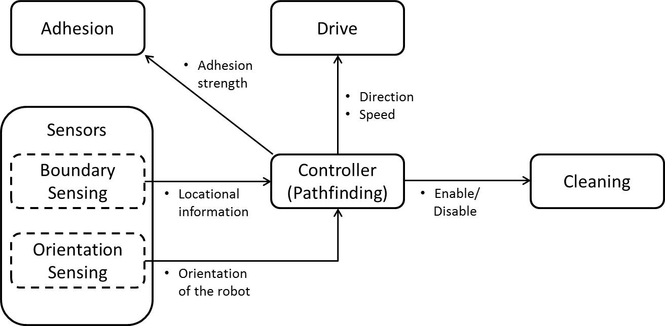
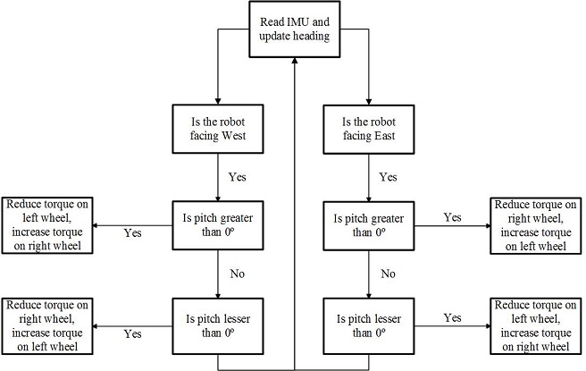
 Figure 1: System's Major Functions and Flow
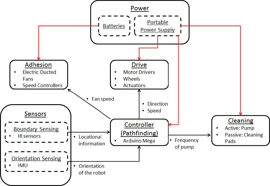
System
Description & Depiction
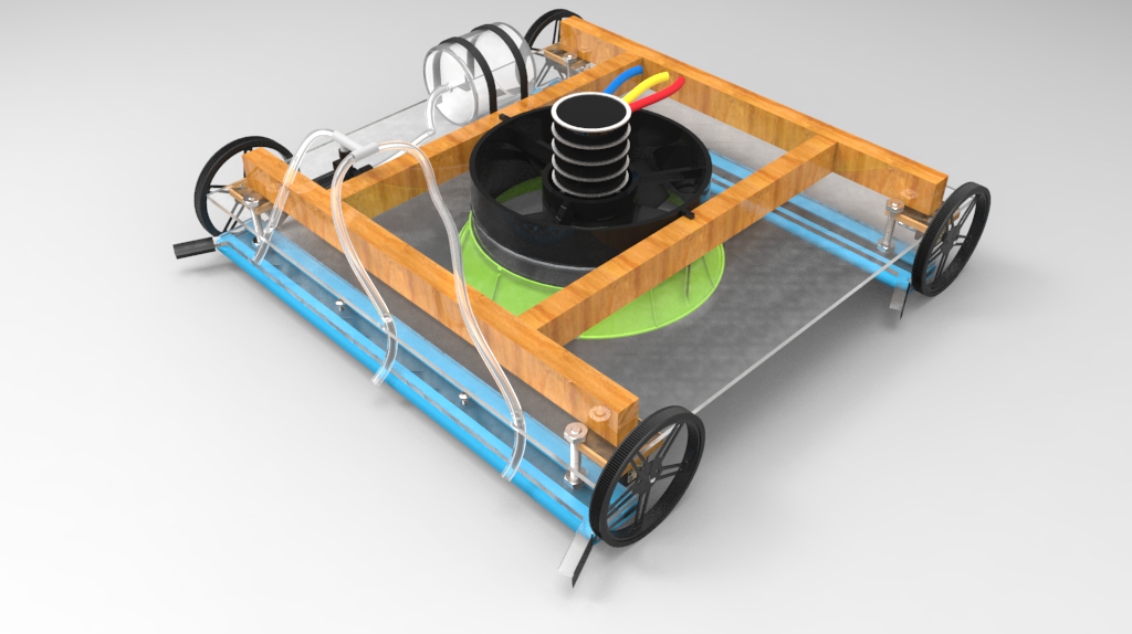
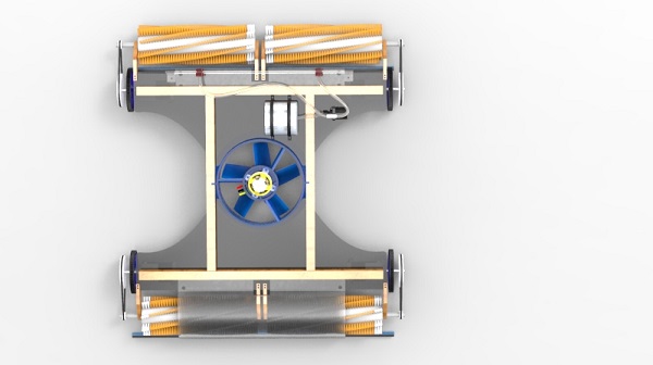
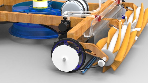
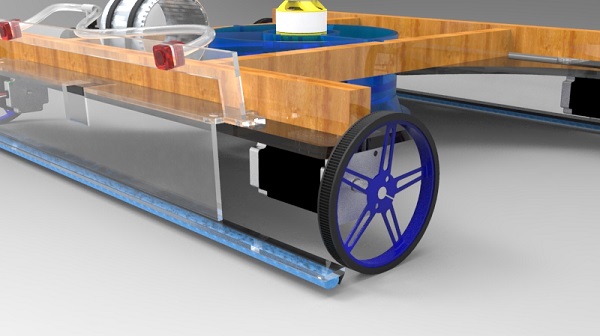
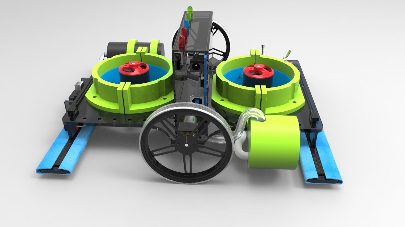
The system is modelled after a racecar, with a two-wheeled chassis and a suction fan mounted in the center. It utilizes a passive cleaning mechanism in which cleaning solution is sprayed in front of the robot and wiped by the microfiber cloth. Below is a 3D render of RACER.
Click and drag to move the 3D render!
-
Controller
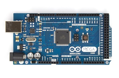
The main controller used will be an Arduino Mega. It has several features, such as 54 digital I/O and 16 analog I/O channels, 256 KB of storage, and 8KB of RAM.
-
Adhesion
The chassis is made of 1/8" laser cut acrylic and measures about 9" by 7" .The robot is held normal to the wall with the use of two 3" electric duct fans.
-
Drive
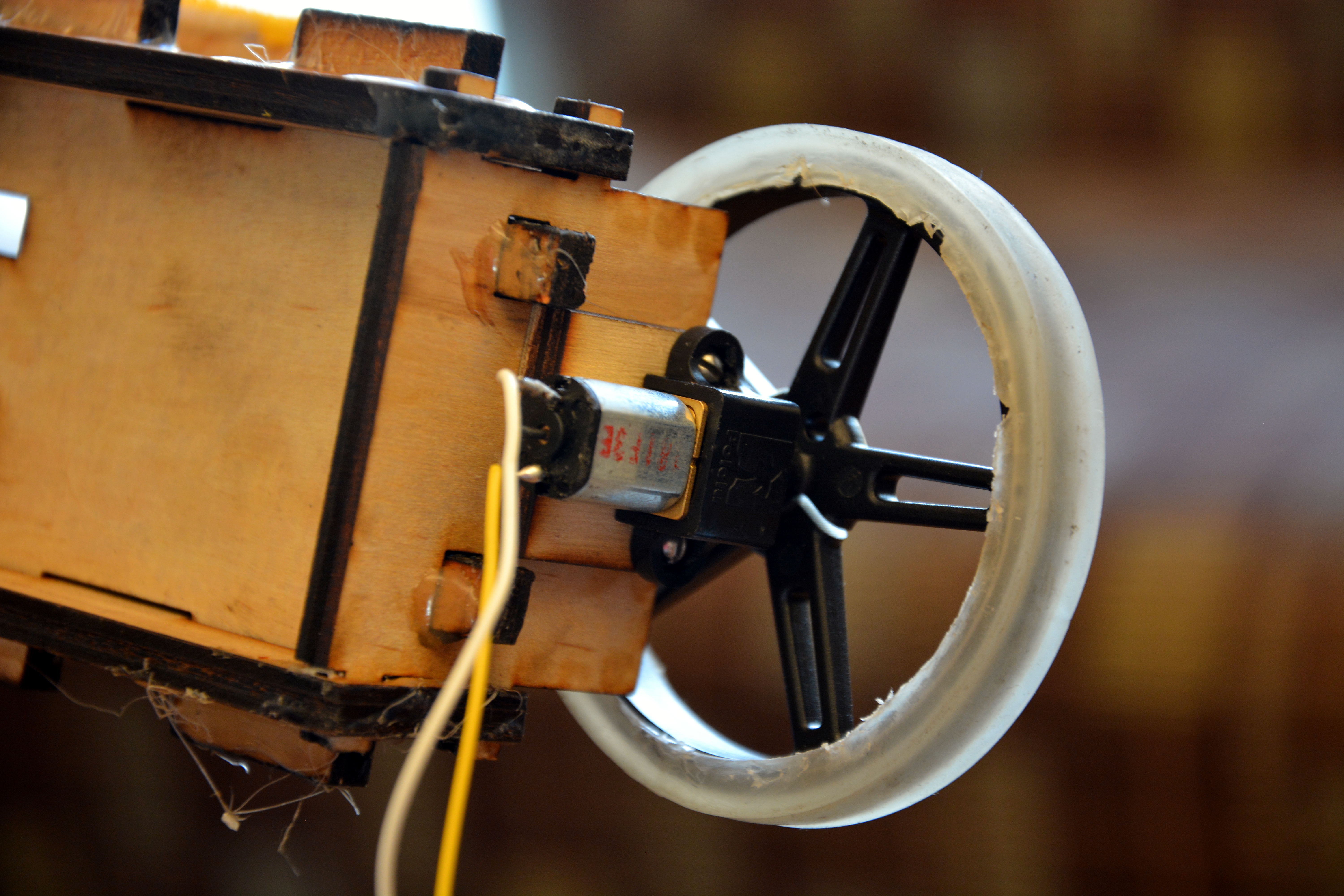
Two DC motors are used to drive the wheels of the robot as shown. The robot would use differential steering to navigate the corners.
-
Sensors
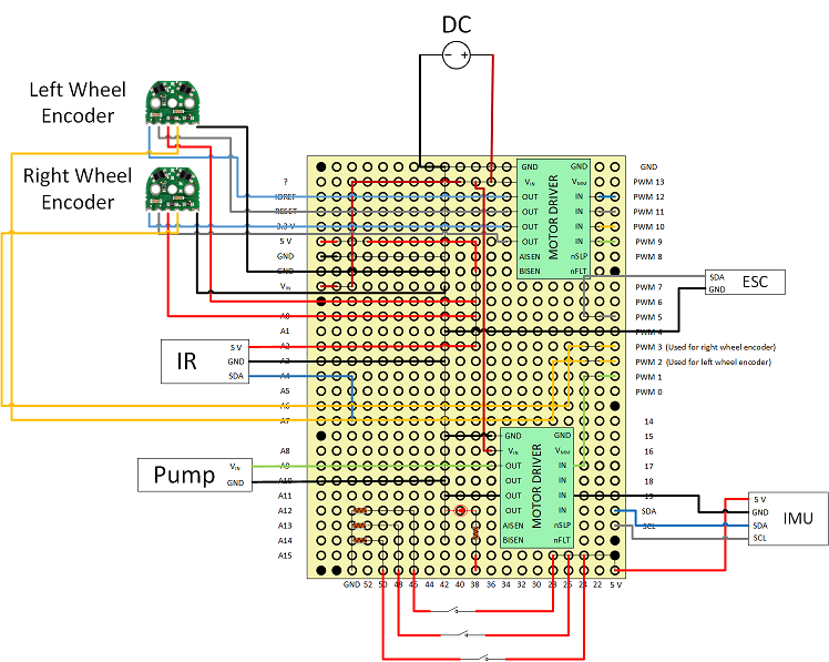
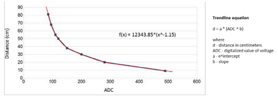
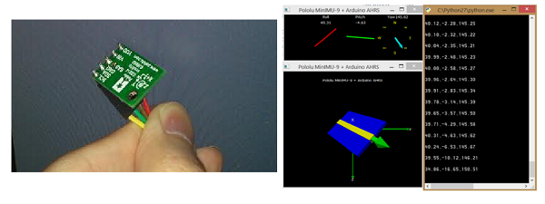
To allow for more precise maneuver near the boundaries, we are using Sharp GP2Y0A21YK0F Analog Distance Sensor with a range of 10 to 80 cm. The IR sensor is placed in front of the robot, between the two nozzles. We are using Popolu MinIMU-9 v3 to measure and calculate the orientation of the robot.
-
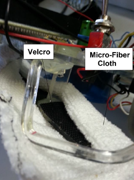
Cleaning
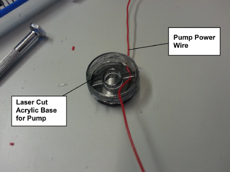
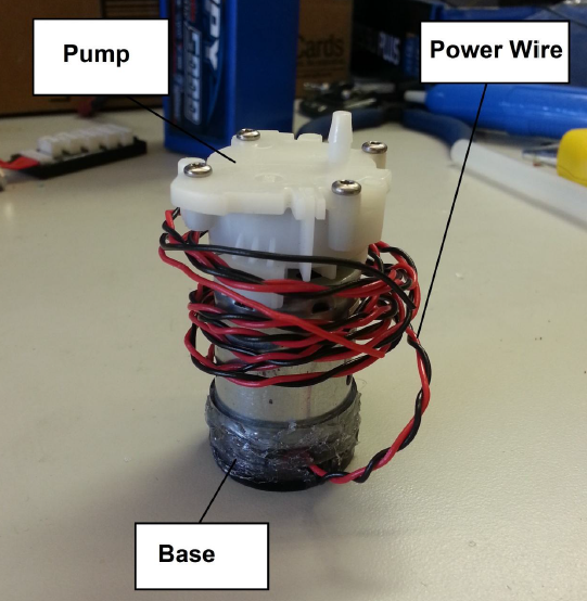
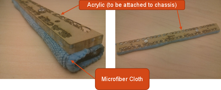
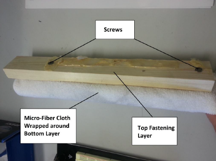
RACER adopts passive cleaning system. This system consists of two cleaning extensions that extend below the robot and make contact with the window. These extensions are thin pieces of acrylic with industrial strength Velcro on the top side. The cleaning cloth is doubled up, and wrapped around the acrylic and attaches to the Velcro. The cleaning system also contains a pump to apply the cleaning solution to the window. The pump is timed to spray the fluid at intervals such that it minimizes the use of the cleaning fluid.
-
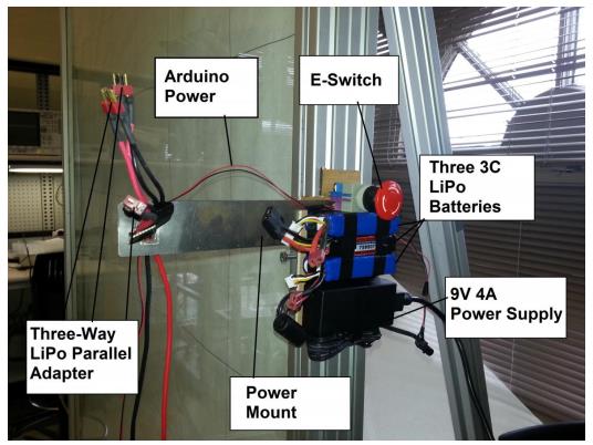
Power
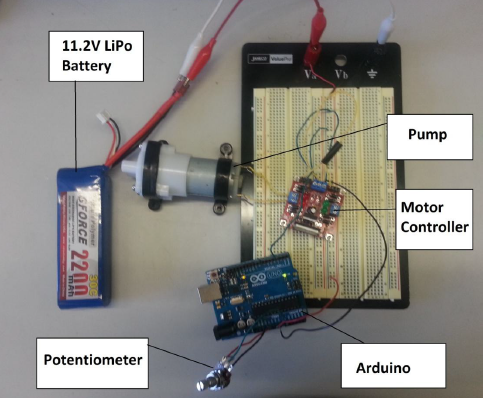
The power harness comprises of three 3S batteries connected in parallel, an emergency switch, and a 9 volts power supply. The power supply provides power for the Arduino, motors, and pump. The wires from the power supply are fed through an emergency switch, allowing us to kill the power to the Arduino immediately in the event of an emergency.
Development
- Controller
- A microcontroller is required to interface with the motors, sensors and cleaning mechanism. Given analog inputs and outputs required by motors and sensors, we have selected two primary options – Arduino Mega and TI MSP430 LaunchPad. Some advantages of Arduino Mega include a massive online community support and libraries which would accelerate our robot’s development. Furthermore, the Arduino Mega has a lot more I/O pins as compared to TI MSP430 which can be helpful given the number of sensors and motors we are using.
However, the TI MSP430 is much cheaper and has more flexible PWM controls as it uses a 16 bit timer rather than ATMega328P’s 8 bit timer. Furthermore, the TI MSP430 has a low power draw features which allow us to consider the possibility of battery-supported operation.
Given the complexity of our prototyping and possibly high I/O pins requirement, we have selected Arduino Mega as our microcontroller. - Boundary Detection
- There are primarily three types of sensors – tactile, proximity and visual – that fulfill the function of detecting a window edge. We evaluated these sensors based on three criteria: accuracy, range and ease of implementation. Accuracy refers to the sensor’s ability to detect the window boundary; a sensor’s range is evaluated based on its maximum and minimum operational range; the ease of implementation is dependent on the ease of processing the information a sensor returns.
By requiring direct physical contact with an object to trigger a tactile sensor’s response, a tactile sensor is deemed to be more accurate than a proximity sensor. The increased accuracy allows for more precise movement at the boundaries of the window. However, a proximity sensor has greater range than tactile sensor and provides additional information (such as the distance between the edge and the sensor). This helps us in fine-tuning movements near the boundaries
Visual sensors have the advantage of increased range as well as an additional capability of differentiating between a window edge and unexpected obstacles. However, the implementation of visual sensor is more complicated than tactile and proximity sensors, severely discounting its effectiveness and efficiency.
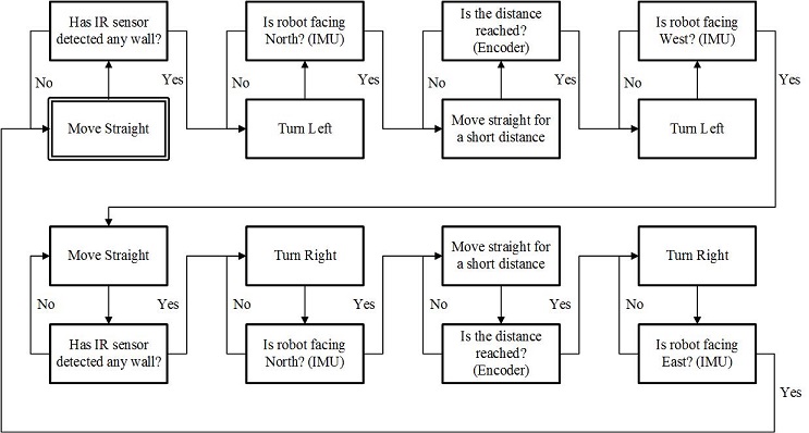
Based on the comparison, we chose to utilize tactile and proximity sensors for our robot. - Path-finding
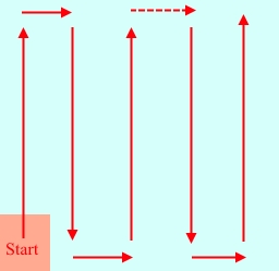
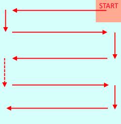
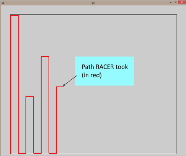
- To meet the project’s requirement of cleaning the window completely, there are several methods the robot can utilize. Such methods include a more thorough method, as well as a “search-and-clean” path-finding algorithm.
For the first and more thorough method, the robot will run through the entire window, cleaning every point regardless of the current cleanliness. On the other hand, another algorithm the robot can employ would be searching the window for dirty spots before cleaning it. The primary criteria used to evaluate these options would be the time required for the robot to complete its task. As the project requires the robot to clean at least 10 ft2 per minute, we chose the first method. This ensures the robot is able to consistently cover the entire span of the window within a certain amount of time over several runs.
In comparison, the search-and-clean methods require the robot to detect dirty spots before cleaning up the window. To accomplish that, the robot will still have to run through the entire window at least once. Hence, the search-and-clean method is deemed to be slower as the robot have to take on the extra task of analyzing the window for dirt. - Grip
- Several methods of generating grip to the window were investigated and analyzed for their advantages and disadvantages with regard to the objective task. Possible adhesion sources include the use of gecko adhesive pads, suction cups, vacuum fan suction, and magnets.
Gecko adhesives pads are a biologically inspired synthetic adhesive that creates adhesion via van der Waals intermolecular forces. Gecko adhesives are advantageous because of their property of being directionally controllable. However, the disadvantages of gecko pads in terrestrial applications outweigh the advantages because the max shear, normal, and moment loads are an order of magnitude smaller than that of suction cups.
Suction cups are a more appealing alternative for gecko pads because they are also fairly easy to actuate and toggle between ON and OFF states whilst offering significantly more adhesive strength. However, suction cups can create a suction that requires significant pull-off force to disengage. This is highly undesirable for a climbing robot where a large pull-off force could destabilize the robot, causing the entire robot to fall off on the window.
An electric ducted vacuum fan (EDF) offers similar advantages to suction cups, such as high adhesive strength and ease of actuation.A vacuum fan offers the potential to be much faster than a robot that employs suction cups. A robot with EDF can use a much simpler wheeled locomotion strategy while the fan runs continuously to create a constant normal force into the window plane for ‘grip’. However, the EDF is unable to generate as much suction force as a static sealed suction cup can. Hence, a disadvantage of this method is that the robot will have to be very light weight.
The final option considered was the use of magnets to create adhesion to the climbing surface. There have been previous climbing robots that make use of electro magnets to climb. However, this constrains the robot’s climbing surfaces to strictly ferromagnetic materials (glass is not a ferromagnetic material). Alternative methods employing magnetic forces would require magnets on both sides of the window which would introduce further complexity and reduce real-world practicality of operation.
Thus, with all things considered, it was decided that the EDF vacuum fan would be used as the source of creating grip. - Movement
- There are two main options to enable the robot to move about the window – a wheeled chassis or by suction caps.
The chassis consists of 4 wheels each driven by independent small brushed DC gear motors. The 4 independent motors will enable torque vectoring to drive forward, backward, and turn in place. Alternatively, treads could be used to generate a larger contact area between the robot and the climbing surface for better steering control. The trade-off for treads would be increased weight in the drive mechanism. Thus, treads are not ideal for an application where weight is a critical factor.
If the suction cup grip method was chosen, then 4 suction cups could be used in a ‘+’ configuration where at least two suction cups will always be engaged to the wall surface at all times. The pairs of suction cups adhered to the wall will alternate and the pair of suction cups not adhered will be slid up, down, left, or right relative to the adhered pair using two rack and pinion mechanisms.
With the use of the EDF vacuum grip method, the locomotion method can be simplified to a basic wheeled chassis. A wheeled chassis complements the choice of EDF as the main adhesion method, and enables the robot to have better mobility around the window. - Cleaning
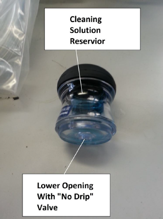
- There are two components to the cleaning subsystem. The cleaning subsystem requires a method to dispense cleaning solution onto the window. Without the cleaning solution, the robot might find it tough to remove certain stains and marks. On the other hand, there are also two different ways our robot can dispense the solution: continuous- or timed-release of solution. Our team decided to choose the latter method, as it allows the robot to minimize the usage of cleaning solution. Hence, this method reduce the amount of solution to be kept on the robot, and consequently reduces the weight as well.
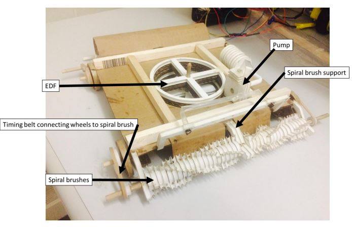
Our team have also narrowed down the method of cleaning to three choices – bristle brushes, spiraling multi-brush, and a passive squeegee. A passive squeegee would be the easiest to install, but the resulting cleanliness leaves much to be desired. Hence, the squeegee is ranked the worst of the three methods. Between bristle brushes and spiraling multi-brushes, the level of cleanliness is deemed to be comparable. However, the spiraling multi-brushes are harder to actuate as compared to bristle brushes. Hence, our team decided that our robot will employ the bristle brush as the main cleaning method.
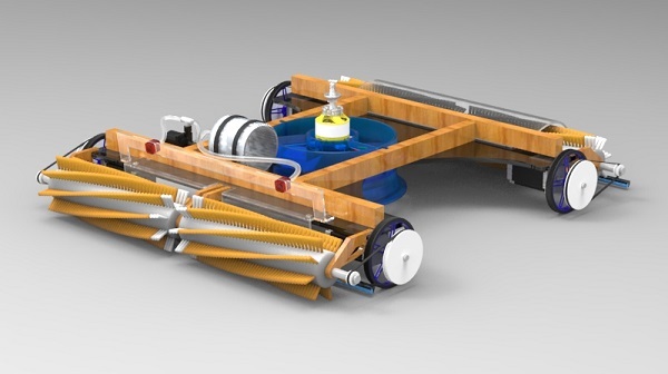
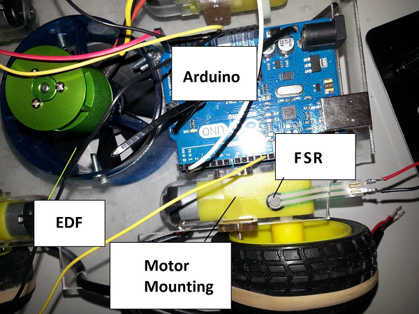
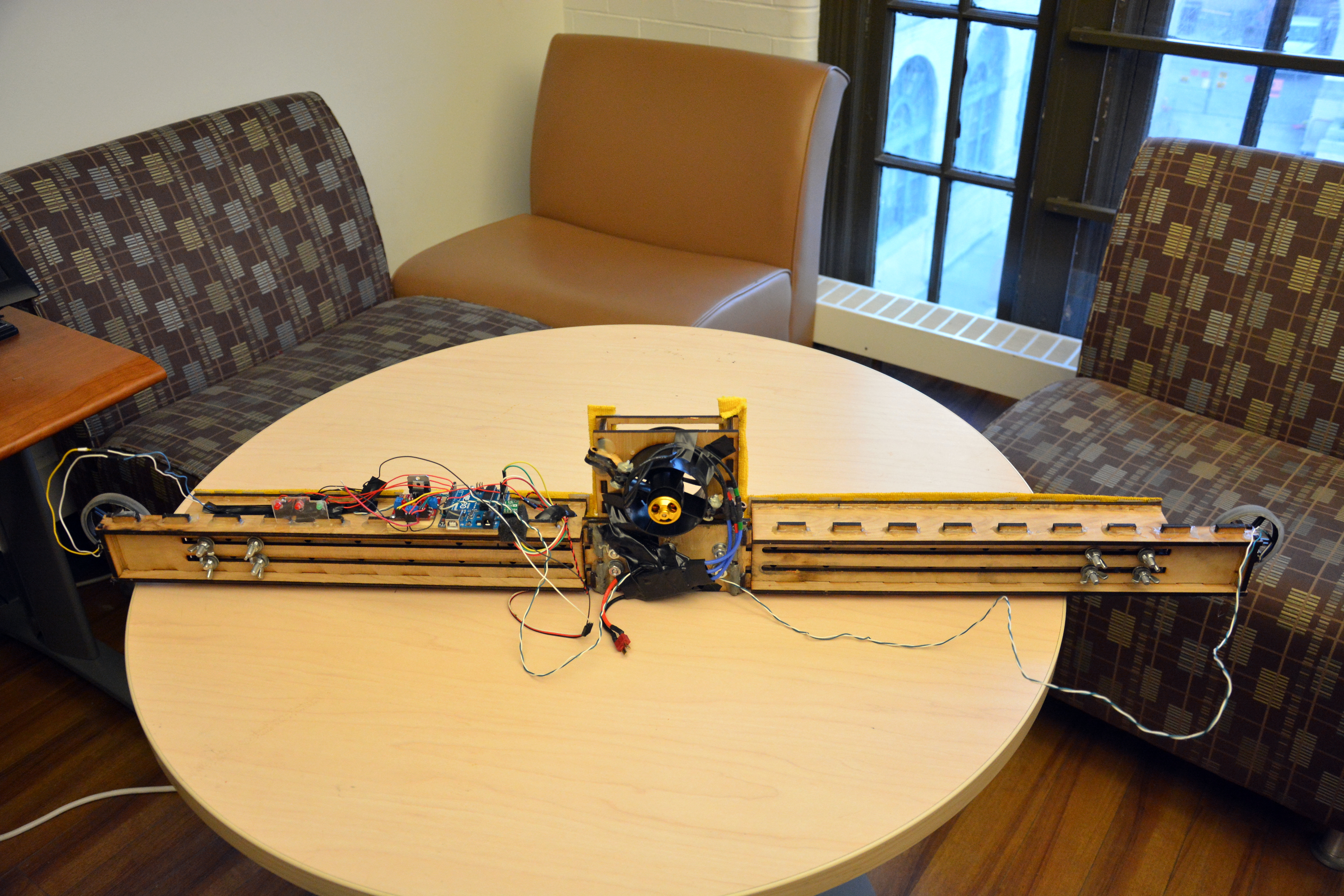
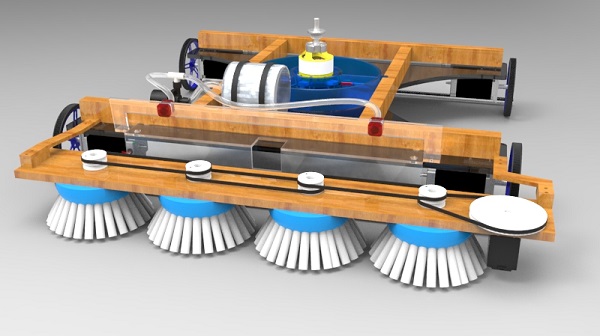
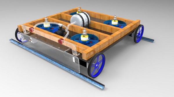
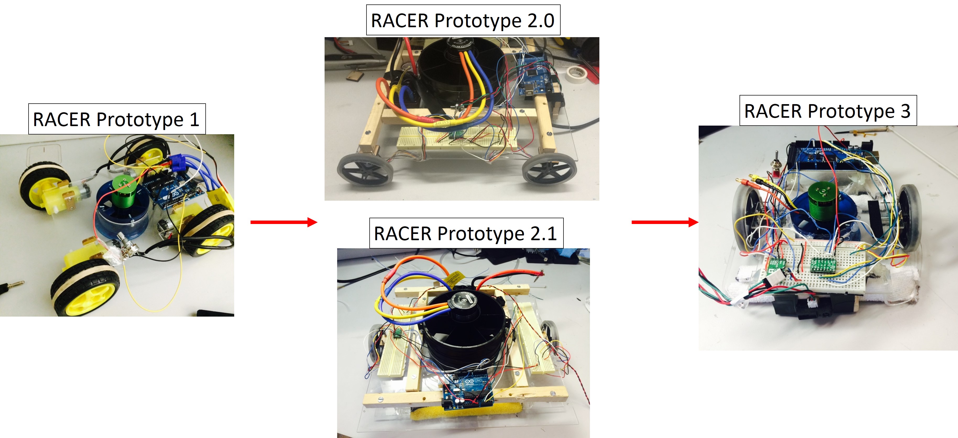
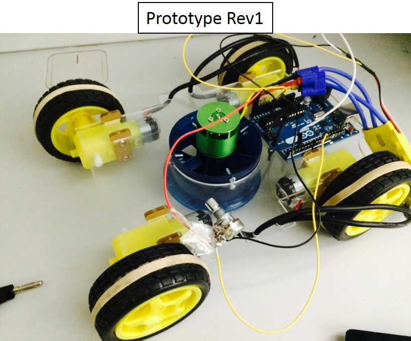
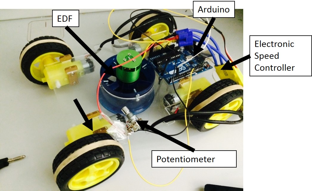
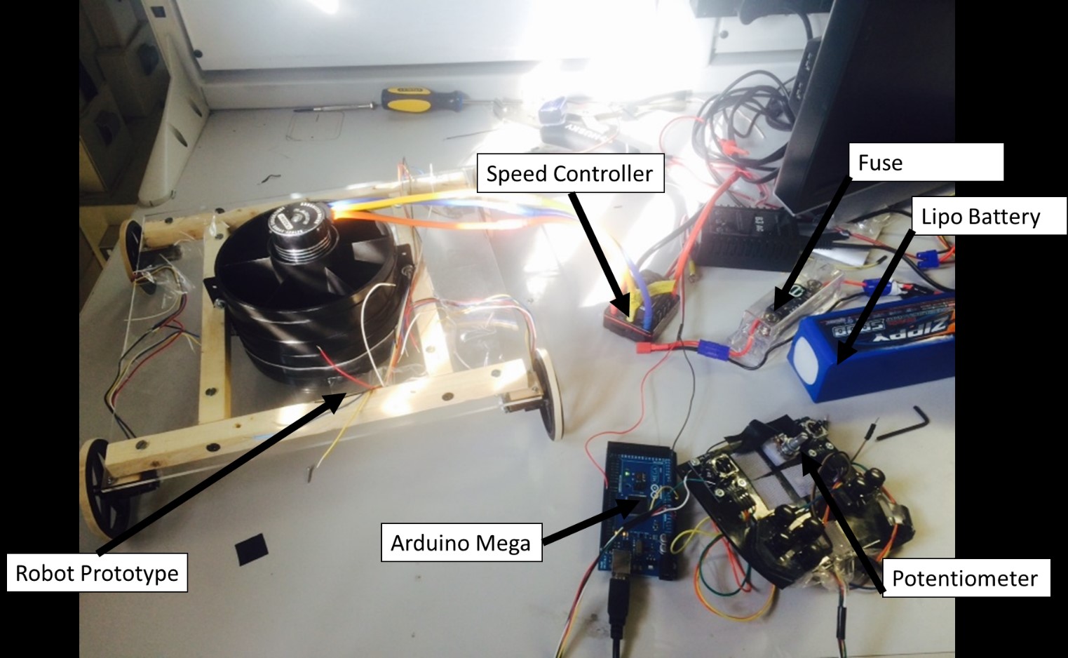
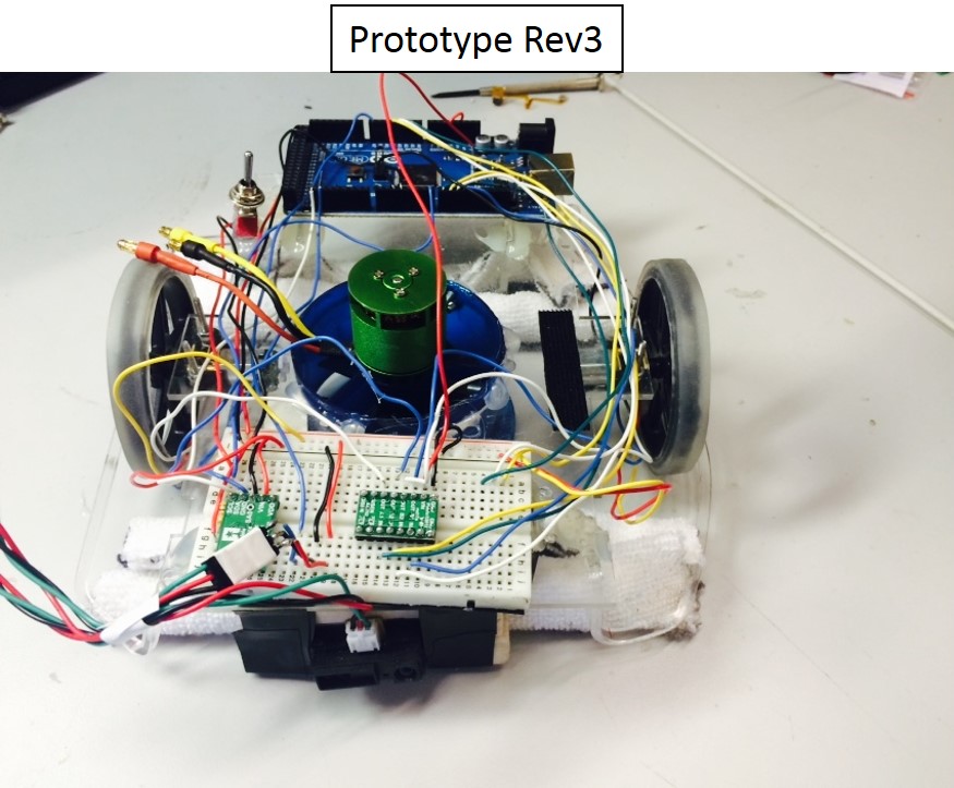
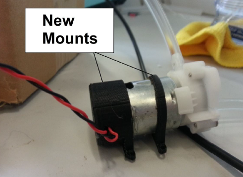
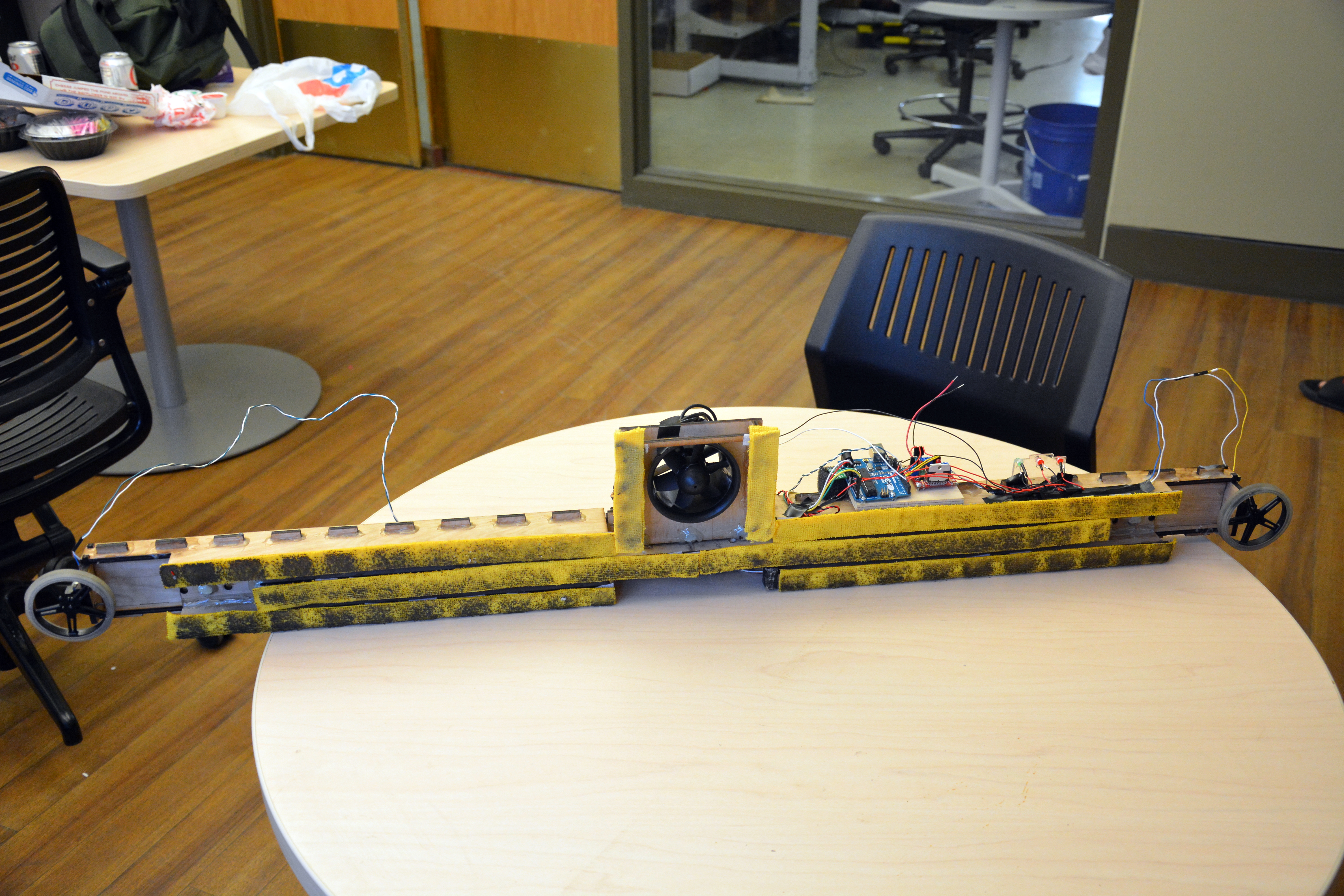
Figure 4 shows a snapshot of our development progress. We have iterated through 3 designs, improving on different sub-systems.
![]()
Figure 4: Snapshot of RACER development
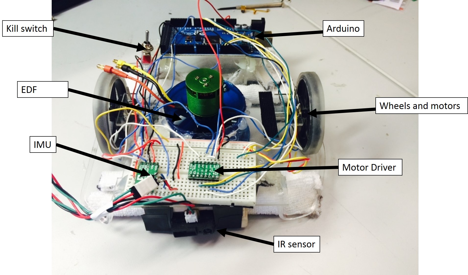
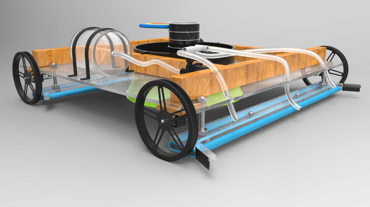
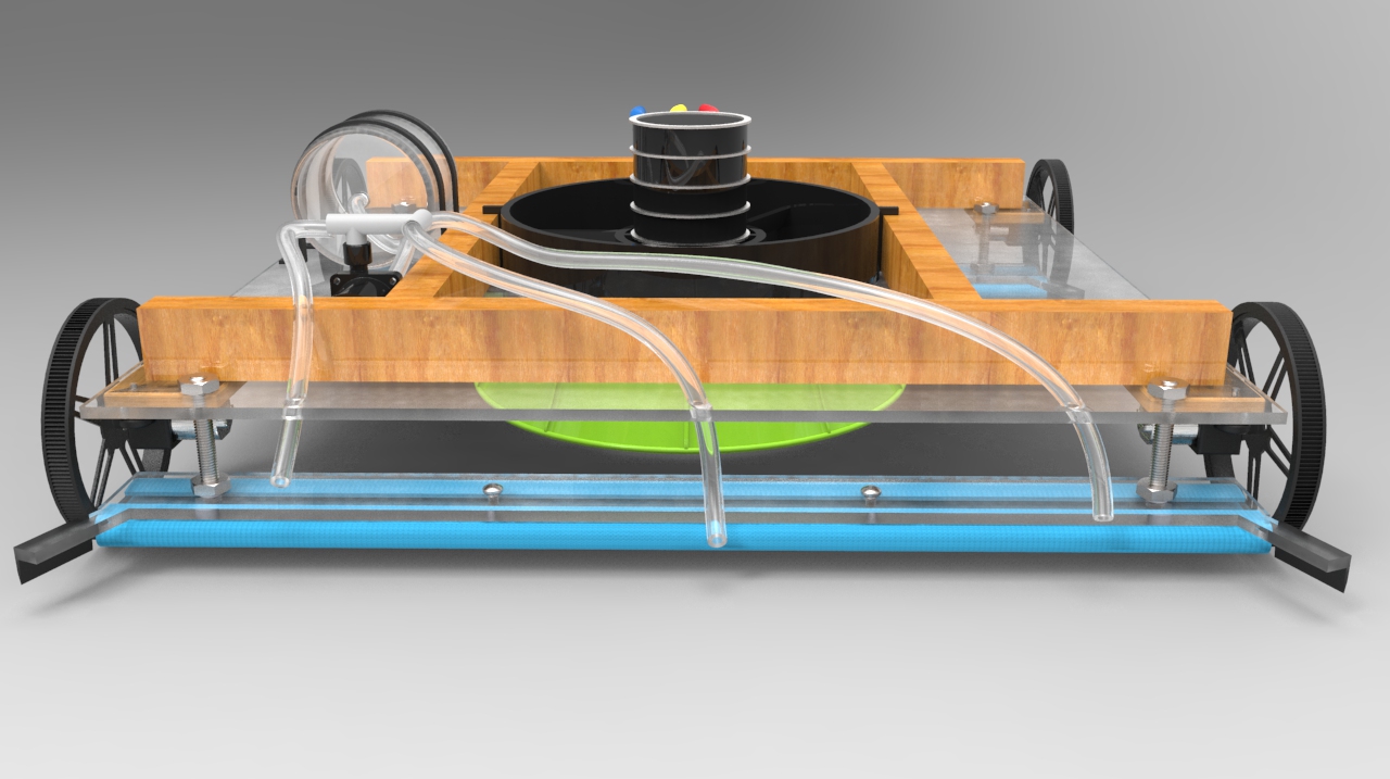
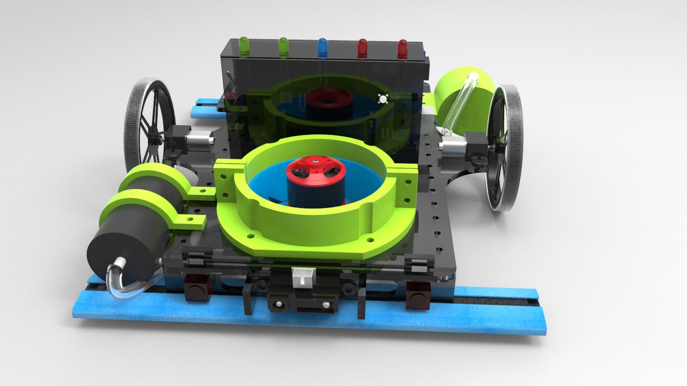
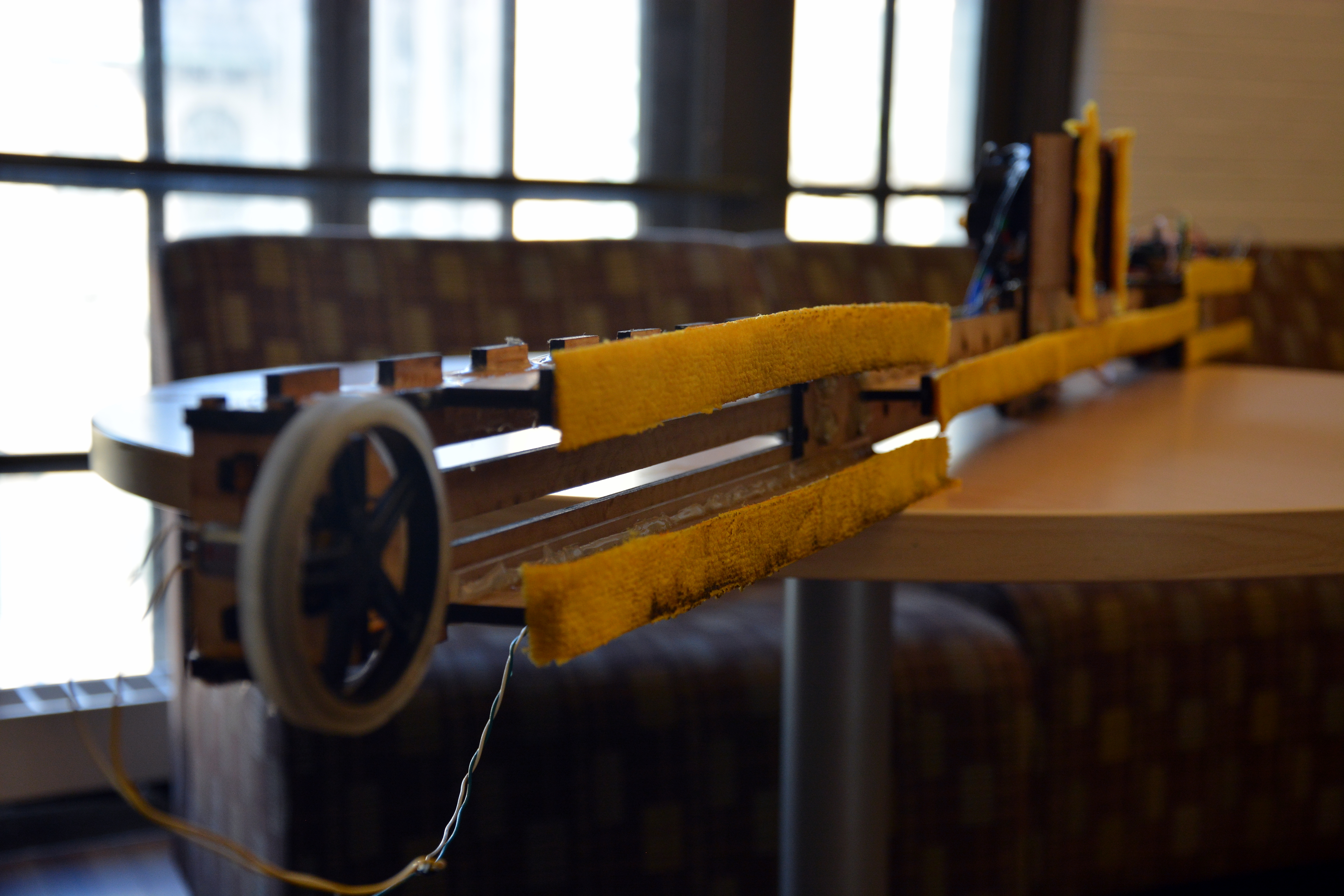
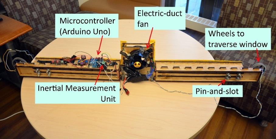
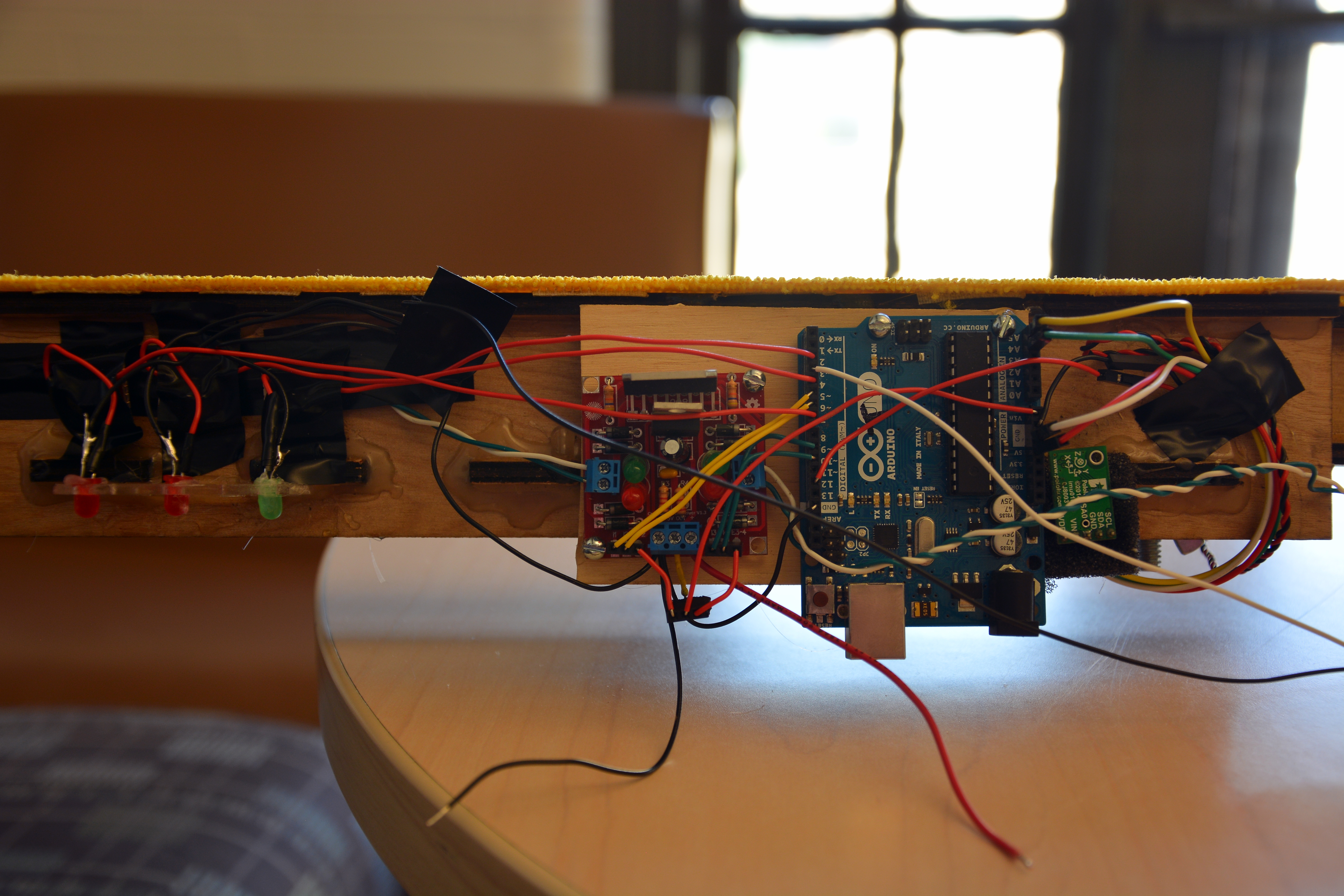
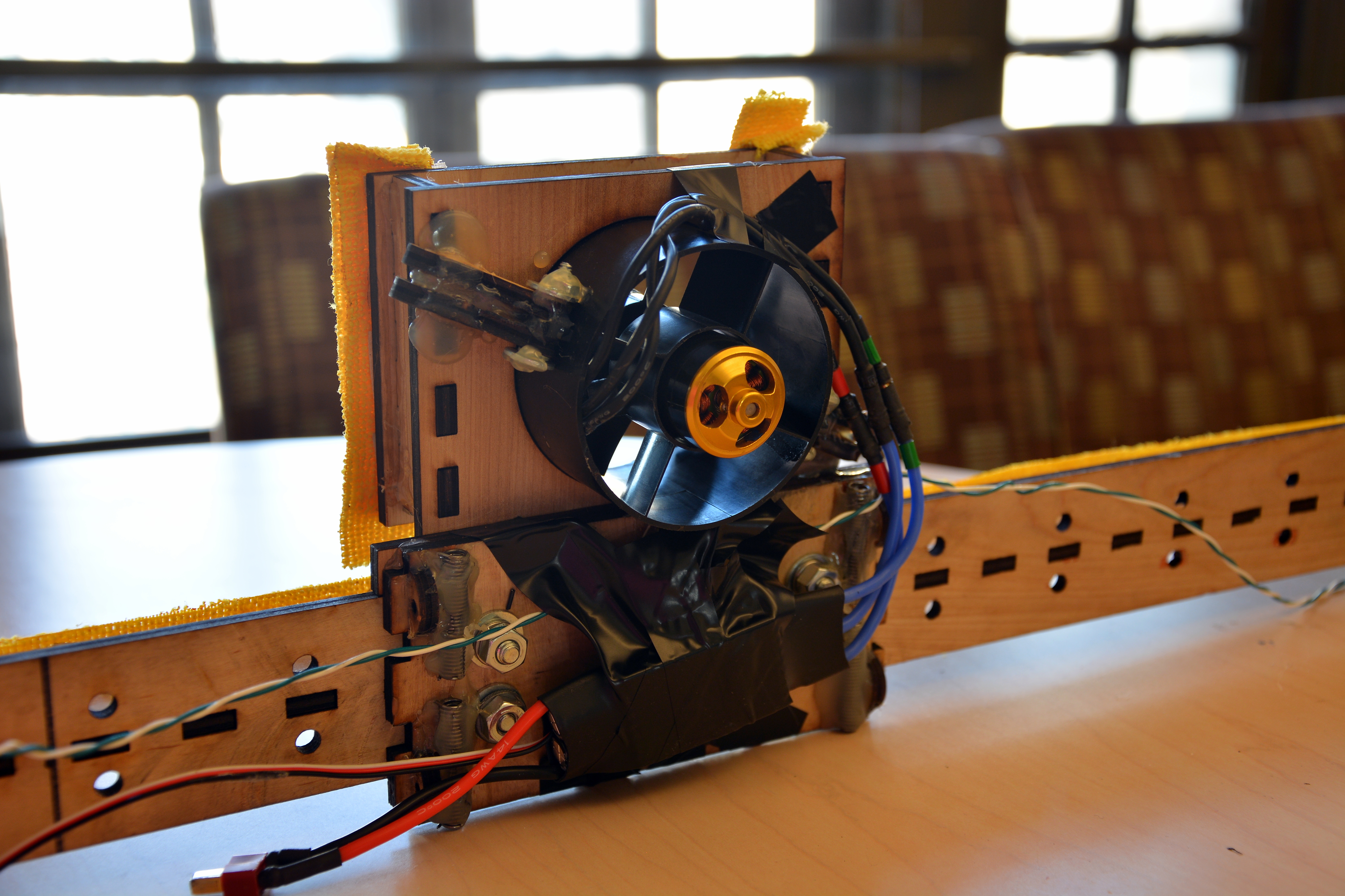
Figure 5 illustrates the final design of RACERand its different sub-systems and components involved.
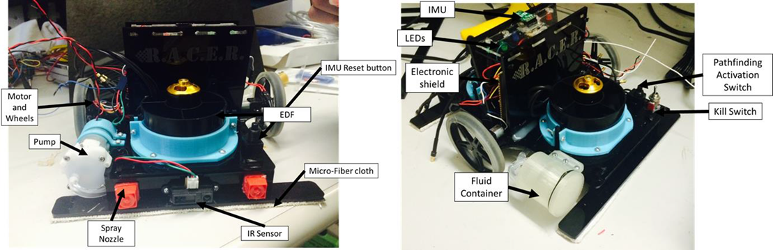
Figure 5: Overall System Depiction of RACER
Left: Front View of RACER. Right: Back View of RACER.


